The Anglemaster® can be used wherever there is a need for a precise measurement of angles and slopes. Scientific research, appliance repair and installation, machinery, woodworking, aerospace, marine, motion picture equipment, bicycle repair, and physical therapy are just a few of the possible applications. The information below is a step by step guide on how to use the Anglemaster® in measuring driveline angles to avoid vibration problems associated with incorrect driveshaft and u-joint working angles. You may also view the "Measuring Driveline Operating Angles" video for free or purchase the DVD with a credit card for $10 + shipping and handling.
Step by Step Guide to Measuring Angles
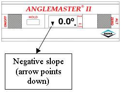
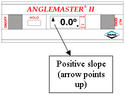
The slope at which a driveline component is installed is a slope of inclination. It is considered either positive or negative depending on whether the slope points up or down when viewed from the transmission toward the rear of the vehicle. A negative driveline slope points down, while a positive driveline slope points up.


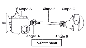
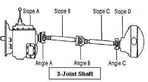
The operating angle of a u-joint is the relationship between two slopes, such as the transmission slope and the tube slope. If you imagine two lines parallel to each component, the angle where these two lines meet is the operating angle. (Angle A, Angle B, Angle C).

High angles combined with high RPMs result in serious vibration problems and reduced u-joint life. Driveline angles should be equal to or within 1° of each other. When checking driveshaft angles, be sure all tires are inflated to their normal operating pressure. Park the vehicle on the surface which is as nearly level as possible both from front to back and from side to side. Also remember to check driveshaft angles while the vehicle is unloaded, and again when it is loaded. This can tell you a lot about operating vibrations that are only present under certain conditions.

To obtain the operating angles of your total driveshaft requires making measurements of the transmission slope, secondary driveshaft slope (if present), and axle slope.
Using your Spicer Anglemaster® II or Anglemaster® Pro digital driveline inclinometer, determine the operating angles by placing the instrument on the driveline components. Begin with the transmission and work toward the axle.
To calculate operating angles with the Spicer Anglemaster® II or Anglemaster® Pro, follow these five easy steps:
- Place the unit on the first slope (Slope A) and allow the reading to stabilize approximately 10 seconds.
- Push the "Alt Zero" button.
- The display will read 0.0° and the "Alt Zero" button indicator will flash. The slope you are using will be the new reference.
- Move the unit to the next adjacent slope (Slope B). The reading obtained is the operating angle of the two slopes (Angle A).
- To obtain additional operating angles, push the "Alt Zero" button again, and then repeat the above process starting at the second slope (Slope B as the Alternate Zero and measure Slope C to get Angle B).
NOTE: For maximum universal joint life, angles should be 3° or less.
